4DOF Robotic Arm DIY Tutorial: A Progressive Guide from Potentiometer Control to Inverse Kinematics
A step-by-step guide to upgrading a DIY 4DOF robotic arm from potentiometer control to inverse kinematics.
This tutorial outlines a complete progression path for a DIY 4DOF robotic arm, covering the transition from manual potentiometer control to Python serial communication, inverse kinematics solving with ikpy, simulation using PyBullet with URDF models, and optional vision-based grasping with OpenCV. Ideal for Arduino robotics beginners looking to systematically upgrade their projects.
A Sophomore's Robotic Arm Project
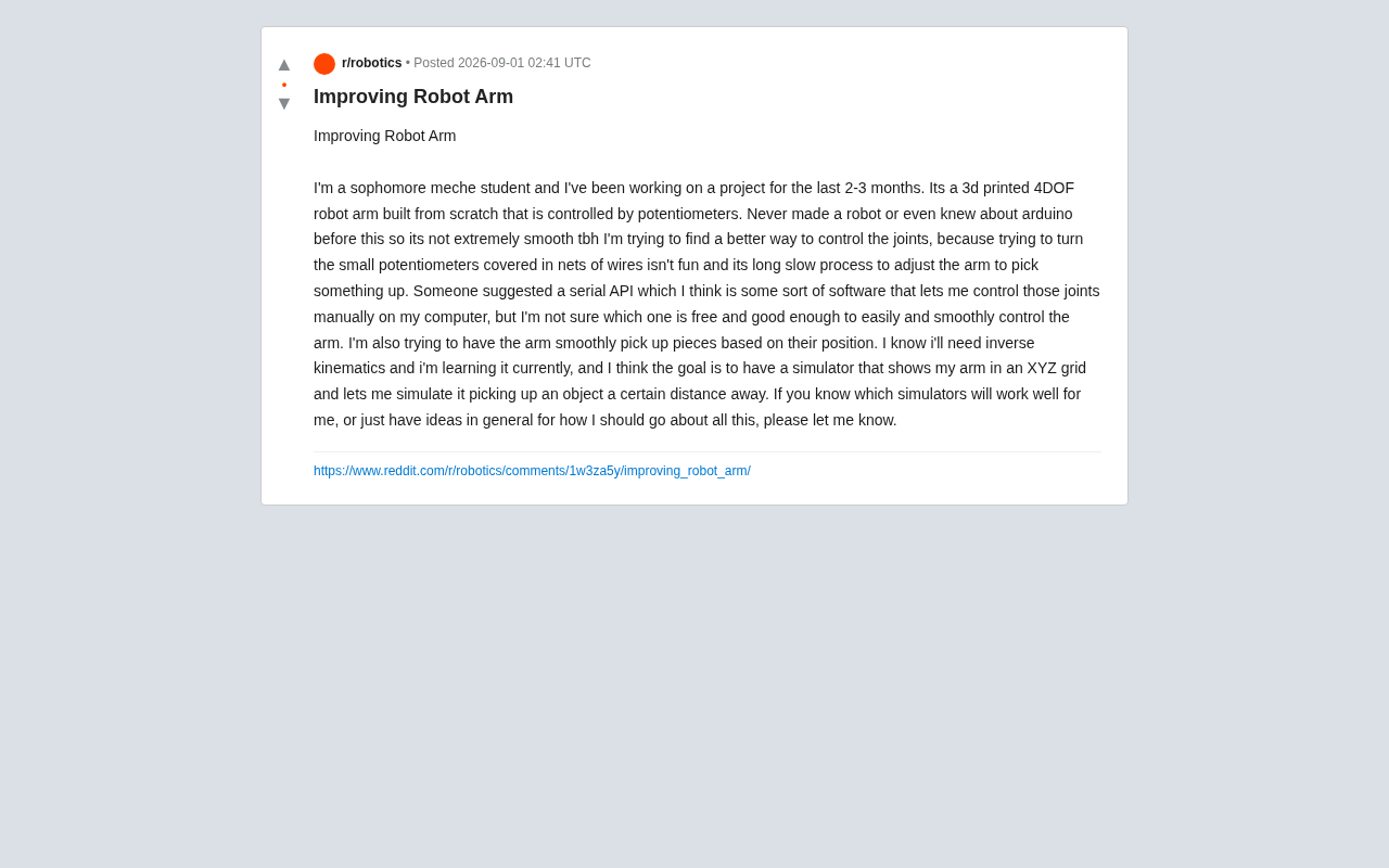
With the growing accessibility of open-source hardware and 3D printing, more and more students and hobbyists are attempting to build their own robots from scratch. Recently, a sophomore majoring in mechanical engineering shared his project on Reddit: a fully self-designed, 3D-printed 4-degree-of-freedom (4DOF) robotic arm, controlled using potentiometers.
Degrees of Freedom (DOF) is the core metric for describing a robotic arm's range of motion, referring to the number of independent directions or axes along which the arm can move. Industrial-grade robotic arms typically have 6DOF (such as those from ABB, KUKA, and other brands), enabling full control of both position and orientation in three-dimensional space. 4DOF means this robotic arm has 4 independently controllable joints, typically including base rotation, shoulder pitch, elbow pitch, and end-effector (e.g., gripper) open/close or rotation. While 4DOF can't achieve full spatial orientation control, it's sufficient for simple pick-and-place tasks, and offers a moderate level of complexity in both mechanical design and control algorithms — making it an ideal entry-level learning project.
Here's an interesting detail: before starting this project, the creator had never worked with robotics and didn't even know what Arduino was. Arduino is an open-source electronic prototyping platform, introduced in 2005 by the Interaction Design Institute Ivrea in Italy, originally designed to lower the barrier to entry for electronics projects. It consists of a development board based on AVR or ARM microcontrollers and a simplified C/C++ programming environment (Arduino IDE). In the robotics field, Arduino is commonly used as a low-level controller responsible for reading sensor data and driving motors and servos. Its advantage lies in its enormous community — virtually every sensor and actuator has ready-made libraries and wiring tutorials. However, Arduino's computing power is limited (the mainstream Arduino Uno has only a 16MHz clock speed and 2KB of RAM), so for complex motion planning or image processing tasks, it typically needs to work alongside a host computer (such as a PC or Raspberry Pi).
After 2–3 months of experimentation, he successfully got the robotic arm moving. That alone is a valuable engineering achievement. However, as the project progressed, he encountered the typical bottlenecks that many beginners face — clunky control methods, jerky movements, and a lack of intelligent grasping capability.
This article will systematically outline the progression path from "it moves" to "it works well" for an entry-level robotic arm, based on the real problems he encountered.
Goodbye Potentiometers: Upgrading the Control Method
Limitations of Manual Potentiometer Control
Currently, this robotic arm uses multiple potentiometers for manual control of each joint. The author's own words paint a vivid picture: "Twisting those little potentiometers tangled in a web of wires is no fun at all," and the process of adjusting the arm to grab objects is "slow and tedious."
This is an inherent drawback of purely manual analog control. A potentiometer is essentially a variable resistor that maps the knob position to a servo angle. When the degrees of freedom increase to four or more, coordinating multiple knobs simultaneously exceeds what human precision and reaction speed can handle for fine tasks.
Replacing Manual Control with Python Serial Communication
Someone suggested the author use a "Serial API," which actually refers to sending commands from a computer via serial communication to control the robotic arm. This is the right upgrade direction.
Serial communication is one of the oldest and most fundamental data transmission methods between computers and peripherals, sending data bit by bit in sequence. In the Arduino ecosystem, serial communication is typically implemented through a USB cable — the Arduino's onboard USB-to-serial chip (such as CH340 or FTDI) converts USB signals to the UART protocol, establishing a bidirectional data channel between the computer and the microcontroller. Common baud rates are 9600 or 115200 bps. pySerial is the most mature serial communication library in Python, supporting Windows, Linux, and macOS, requiring only a few lines of code to open a serial port and send/receive data. The core idea of this architecture is to use Arduino as the "execution layer" that only drives hardware, while placing complex logic and user interaction on the "decision layer" — the Python program running on the PC.
The typical implementation path looks like this:
- Arduino side: Write a program that receives serial commands, parses angle instructions like
J1:90 J2:45, and then drives the corresponding servos. - PC side: Use Python's
pySeriallibrary to send commands. Python's ecosystem is mature and free, and combined with simple GUI libraries (like Tkinter or PyQt), you can create a slider control panel that's far more intuitive than turning knobs.
For beginners, starting with Python + pySerial is recommended. It's free, has abundant community resources, and can seamlessly connect to more advanced features like kinematics calculations and visual grasping later on.
Introducing Inverse Kinematics: Teaching the Arm to Grasp Intelligently
What Is Inverse Kinematics (IK) and Why Do You Need It?
The author's next goal is to have the robotic arm "smoothly grasp objects based on their position." This is exactly the core problem that Inverse Kinematics (IK) is designed to solve.
In simple terms:
- Forward Kinematics (FK): Given the joint angles, calculate the spatial position of the end effector (gripper).
- Inverse Kinematics (IK): Given the target XYZ coordinates, determine what angles each joint should rotate to.
When controlling manually, you're essentially "performing IK through eyeballing and trial-and-error," while a computer can solve it mathematically in an instant. For a 4DOF robotic arm, IK typically has two approaches: analytical solutions (geometric methods) or numerical solutions (iterative methods). Analytical solutions use trigonometric functions and geometric relationships to directly calculate joint angles — fast to compute but requiring manual derivation of formulas specific to the arm's structure. Numerical solutions use the Jacobian Matrix to iteratively converge on the target position — more generalizable but potentially facing convergence issues. For a relatively simple structure like 4DOF, analytical solutions are usually preferred — since there are fewer degrees of freedom, the geometric relationships can be decomposed within a 2D plane, keeping the mathematical derivation at a manageable difficulty level.
Learning Recommendations for 4DOF Robotic Arm IK
The author mentioned that he's currently studying inverse kinematics, which is a very wise decision. For a relatively simple 4DOF structure, the following step-by-step approach is recommended:
- Start by manually deriving the analytical solution using geometric methods for 2–3 joints to understand the concepts of joint coordinate systems and D-H parameters. D-H parameters (Denavit-Hartenberg parameters) are a standardized method for describing the geometric relationships of robot links and joints, proposed by Jacques Denavit and Richard Hartenberg in 1955. Each joint is described by four parameters: link length (a), link twist (α), link offset (d), and joint angle (θ). These four parameters are used to construct the homogeneous transformation matrix between adjacent joint coordinate systems. Multiplying all joint transformation matrices sequentially yields the position and orientation of the end effector relative to the base — this is the mathematical foundation of forward kinematics. For beginners, the key to understanding D-H parameters lies in learning to correctly establish the coordinate system for each joint. While this step is conceptually abstract, once mastered, it allows you to convert the kinematics problem of any serial robot into standardized matrix operations.
- Use Python libraries like
ikpyfor quick verification. It can read URDF model files and automatically perform IK solving, significantly lowering the mathematical barrier. - Gradually understand practical engineering issues such as singularity configurations and multi-solution selection. Singularity configurations occur when the robotic arm is in certain special poses where some degrees of freedom degenerate and the Jacobian matrix rank decreases — for example, when two rotation axes are perfectly aligned, the arm "loses" its ability to move in a certain direction. Multi-solution selection is another practical IK challenge: for the same target position, the arm may have multiple valid sets of joint angle combinations (imagine your human arm reaching the same point from above or below). Choosing the most reasonable and safe solution requires considering joint limits, motion continuity, and obstacle avoidance.
Choosing the Right Simulation Platform for Your Robotic Arm
The Value of Simulation in Robotic Arm Development
The author wants a simulator that can display the robotic arm in an XYZ grid and simulate grasping objects at a certain distance. Simulation is immensely valuable during actual debugging — it allows you to validate control algorithms, visualize motion trajectories, and identify collisions and out-of-bounds issues without risking hardware damage. This is especially important for 3D-printed robotic arms: servo stall overloads can burn out motors or damage gearboxes, and printed parts are prone to breaking under unexpected forces. Running algorithms in simulation first can dramatically reduce the cost of trial and error.
Comparison of Three Mainstream Simulation Tools
Given this student's needs and technical level, the following tools are worth considering:
- PyBullet: Lightweight, free, with native Python support. Import a URDF model and you're ready to simulate. Rich community tutorials make it ideal for entry-level robotics projects and IK verification. PyBullet is a Python wrapper around the Bullet Physics SDK, developed and maintained by Erwin Coumans, and was heavily promoted by the Google Brain team for reinforcement learning research. The Bullet engine itself is an open-source real-time physics simulation library widely used in game development and visual effects. PyBullet builds on this with robot-specific simulation features: support for loading URDF/SDF/MJCF model formats, built-in forward and inverse kinematics solvers, collision detection, friction simulation, and joint torque control. Installation requires just a single
pip install pybulletcommand, and all APIs are pure Python calls, making it an ideal choice for rapid prototyping. - Gazebo + ROS: Powerful and professional — the mainstream choice in both academia and industry, but with a steep learning curve that may be too heavy for a beginner project. ROS (Robot Operating System) is not a traditional operating system but rather a framework and toolset for robot software development, including hardware abstraction, message passing, and package management. As the default physics simulator in the ROS ecosystem, Gazebo can simulate complex multi-robot scenarios, various sensors (LiDAR, depth cameras, etc.), and realistic physical interactions. However, its installation and configuration process is relatively complex, and it primarily relies on a Linux (Ubuntu) environment, placing high demands on a newcomer's ability to set up development environments.
- CoppeliaSim (formerly V-REP): User-friendly graphical interface with a built-in IK solver. The educational version is free and suitable for quickly building visual scenes.
Overall, PyBullet offers the best value as a starting point. It forms a unified tech stack with Python serial control, ikpy, and other tools, avoiding the need to switch between multiple languages and frameworks.
Building a URDF Model: The First Step in Simulation
Regardless of which simulation tool you choose, you'll need to create a URDF model for your robotic arm first. URDF (Unified Robot Description Format) is an XML-based robot model description standard defined within the ROS ecosystem. A URDF file fully describes the physical structure of a robot, including the geometric shape, mass, and moment of inertia of each link, as well as the type (revolute, prismatic, fixed, etc.), range of motion, and parent-child link relationships of each joint. Although URDF was originally designed for ROS, its clean and versatile format has led to adoption by many simulation and computation tools, including PyBullet, MuJoCo, and ikpy. For DIY robotic arm projects, writing a URDF file requires measuring the actual length of each link segment, determining the rotation axis direction and angle limits of each joint, and then organizing this information using XML tags. If your robotic arm is 3D-printed, you can export STL mesh files of the links directly from your CAD model and reference them in the URDF as visual and collision geometry — this way, the robotic arm in simulation will closely match the physical appearance of the real thing.
Four-Stage Progressive Roadmap for DIY Robotic Arms
Based on the author's situation, the following staged approach is recommended:
- Stage 1: Serial Control — Replace potentiometers with Python + pySerial. Start by implementing computer-based slider control to solve the "hard to operate" pain point. The core of this stage is establishing a reliable communication link between the PC and Arduino and designing a clear command protocol. Adding a command acknowledgment mechanism (Arduino sends back a confirmation signal upon receiving a command) is recommended to prevent abnormal movements caused by data loss.
- Stage 2: Simulation Modeling — Build a URDF model for the robotic arm and set up a PyBullet simulation environment to visualize joint movements.
- Stage 3: Inverse Kinematics Solving — Integrate ikpy to implement inverse kinematics, enabling the robotic arm to automatically position itself based on XYZ coordinates. Verify the IK algorithm's correctness in simulation first, then deploy to the physical arm once confirmed.
- Stage 4: Visual Grasping (Optional) — Connect a camera with OpenCV to implement vision-based object recognition and automatic grasping. OpenCV (Open Source Computer Vision Library) is an open-source computer vision library initiated by Intel in 1999, currently maintained by the nonprofit organization OpenCV.org, supporting C++, Python, Java, and other languages. In robotic visual grasping scenarios, OpenCV typically handles image acquisition, preprocessing, and target detection. A typical visual grasping pipeline includes: capturing images through a camera, identifying target objects using color thresholds or contour detection, calculating the object's pixel coordinates in the image, converting pixel coordinates to real-world coordinates through camera calibration parameters, and finally passing the target coordinates to the inverse kinematics solver to drive the robotic arm. For beginner projects, it's common to start with detecting single-colored objects (such as a red block), where HSV color space thresholding can achieve fairly reliable recognition without requiring complex techniques like deep learning.
Final Thoughts: Make It Move First, Then Make It Smart
Although this sophomore's project is admittedly "not particularly smooth" at the moment, the attitude of starting from zero and learning by doing is incredibly valuable. Robotics development is inherently a cross-disciplinary endeavor spanning mechanics, electronics, control systems, and software — very few people get everything right on the first try. This concept is known in academia as "Mechatronics," requiring developers to simultaneously possess skills in structural design, circuit building, embedded programming, and host computer software development. For this reason, robotic arm projects are used by many universities as comprehensive engineering education platforms — they force students to break down the barriers between individual disciplines and integrate multi-domain skills through real-world problems.
From turning knobs to serial control, and then to inverse kinematics and visual grasping, each step represents a leap in capability. For all hobbyists looking to get started in robotics, this path offers valuable guidance: Make it move first, then make it smart.
Related articles

JobRunner MCP Server: AI Agents Can Now Fix Failed Java Jobs
JobRunner launches an open-source MCP server enabling AI agents to view cluster status, diagnose failures, and recover Java jobs—incident response from any cloud coding environment or existing agent.

MLAI Digital Launches 9 Security Agents: MCP Server Safeguards the Full Lifecycle of Agentic AI
MLAI Digital launches Security MCP Server with nine built-in specialized security agents covering vulnerability discovery, attack simulation, prompt injection detection, API and infrastructure assessment, and accelerated remediation—embedding security validation across the full Agentic AI lifecycle from development to production.

Running Isaac Lab on H100 GPUs: Exploring Better Approaches
Exploring optimization methods for running Isaac Lab on NVIDIA H100 GPUs, including MIG configuration, mixed precision, TensorRT acceleration, and community experience to improve robotics simulation and reinforcement learning efficiency.