AI-Powered Engineering Drawing Parsing: Comparing OCR, Object Detection, and Vision-Language Model Approaches
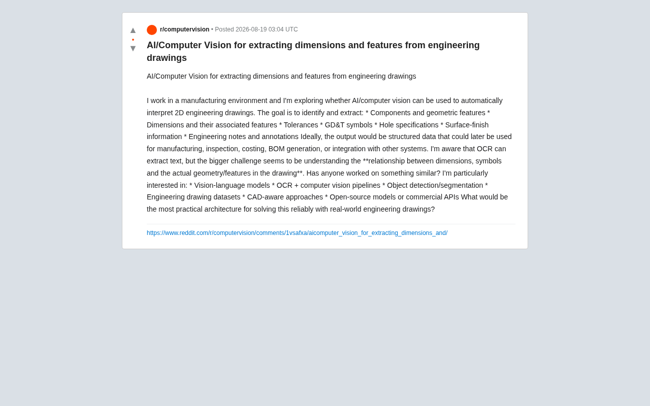
Comparing OCR, object detection, and VLM approaches for AI-powered engineering drawing parsing.
This article examines three major technical approaches for AI-powered engineering drawing parsing: OCR + computer vision pipelines, object detection and semantic segmentation, and vision-language models (VLMs). It analyzes each approach's strengths and limitations for recognizing GD&T symbols, associating dimensions with geometric features, and generating structured output. Given data scarcity and high precision demands in manufacturing, the article recommends a hybrid architecture combining CAD-aware parsing, specialized detection models, and VLMs with human oversight.
In manufacturing's digital transformation, one challenge has long plagued engineers: how do you get machines to "read" 2D engineering drawings? Recently, an engineer working in manufacturing sparked a discussion on Reddit about the feasibility of using AI and computer vision to automatically parse engineering drawings. This topic touches on a core pain point in industrial AI deployment and raises important questions about the comparison between various current technical approaches.
The Real Challenges of Engineering Drawing Parsing
The engineer who raised the question clearly outlined the goal: automatically identify and extract multiple categories of key information from 2D engineering drawings, including parts and geometric features, dimensions and their associated features, tolerances, GD&T (Geometric Dimensioning and Tolerancing) symbols, hole feature specifications, surface roughness information, and engineering notes and annotations.
It's worth elaborating on the GD&T system here. GD&T (Geometric Dimensioning and Tolerancing) is an engineering language system defined by the ASME Y14.5 standard (US) and ISO 1101 standard (international). It uses 14 geometric tolerance symbols (such as position, flatness, cylindricity, coaxiality, etc.) to precisely describe the form, orientation, location, and runout requirements of parts. Unlike traditional plus/minus tolerance annotations, GD&T uses Feature Control Frames to integrate tolerance type, tolerance value, and datum system into a compact graphical symbol. This highly compressed information encoding requires specialized training for human engineers to interpret correctly, and poses an even greater challenge for AI systems — which must not only recognize the symbols themselves but also understand the hierarchical relationships of datum systems and the 3D implications of tolerance zones.
The ideal output should be structured data that can be directly used for downstream manufacturing processes, quality inspection, cost estimation, BOM (Bill of Materials) generation, or integration with other enterprise systems. Structured data refers to data organized according to predefined formats (such as JSON, XML, or database tables), in contrast to unstructured drawing images. In the context of manufacturing digitalization, converting drawing information into structured data is the critical bridge connecting design and manufacturing. A BOM lists all components and their quantity relationships required for a product and serves as the core input for ERP (Enterprise Resource Planning) and MES (Manufacturing Execution Systems). Once drawing information is structured, it can directly drive CNC machining program generation, CMM (Coordinate Measuring Machine) inspection program creation, automated quoting system calculations, and other downstream processes — reducing manual translation steps. This is also an indispensable data foundation in the Industry 4.0 and digital twin vision.
This need is extremely common in manufacturing enterprises — vast quantities of legacy drawings exist as PDFs or scanned documents, and manual data entry is both time-consuming and error-prone.
Here's a notable detail: the engineer astutely identified the essence of the problem: the real challenge isn't OCR text recognition itself, but understanding the relationships between dimensions, symbols, and the actual geometric features in the drawing. Which hole does the dimension annotation "Ø10 H7" correspond to on the drawing? Which datum surface does a particular GD&T frame constrain? This kind of spatial and semantic association understanding is the core barrier in engineering drawing parsing.
Comparing Mainstream Technical Approaches
For the AI parsing of engineering drawings, several technical solutions currently exist in the industry, each with its own applicable scenarios and limitations.
OCR + Computer Vision Pipeline
The most traditional and straightforward approach is building a multi-stage "OCR + computer vision" pipeline. OCR handles text information extraction (dimension values, annotation text), while computer vision algorithms detect geometric primitives (lines, circles, arcs) and symbols.
It's important to note that while Optical Character Recognition (OCR) technology is quite mature in general document processing, engineering drawings present unique challenges. Text and graphical elements are highly intermingled in drawings — dimension numbers are placed right next to leader lines, tolerance values are nested within feature control frames, and annotation text overlaps with section lines. Engineering drawings also use numerous special symbols (diameter symbol Ø, degree symbol °, plus-minus sign ±, surface roughness Ra symbol, etc.) that are underrepresented in standard OCR training sets. Additionally, scanned documents often suffer from skewing, noise, and creases, with older blueprints having particularly poor contrast and clarity. Therefore, engineering drawing OCR typically requires domain-specific fine-tuning on top of general-purpose engines (such as Tesseract or PaddleOCR).
The advantage of this approach is that each module is relatively mature, highly controllable, and easy to debug. However, the drawbacks are also clear: the information silos between modules make "association understanding" difficult. Binding the OCR-extracted dimension "10.5±0.1" to the correct geometric feature often requires additional rule engines or spatial reasoning logic, and the diversity of engineering drawings makes it impossible to enumerate all rules.
Object Detection and Semantic Segmentation
The second path uses Object Detection and Segmentation models specifically trained to recognize standardized elements in engineering drawings, such as GD&T symbols, dimension annotation frames, surface roughness symbols, and welding symbols.
In terms of object detection frameworks, YOLO (You Only Look Once) and Faster R-CNN are the two major representatives in this field. YOLO employs a single-stage detection strategy, combining object localization and classification in a single forward pass, achieving extremely fast inference speeds. The latest YOLOv8/v9 versions have significantly improved accuracy while maintaining high speed. Faster R-CNN is the classic representative of two-stage detection, first generating candidate regions through a Region Proposal Network (RPN), then performing fine-grained classification and bounding box regression on those candidates — typically achieving higher accuracy but at slower speeds. In engineering drawing scenarios, where symbols vary greatly in size (from tiny surface roughness triangle symbols to large title blocks), are densely arranged, and may be occluded, targeted optimizations such as anchor box size adjustment and multi-scale feature fusion are usually needed on top of these general frameworks, along with transfer learning on engineering drawing-specific datasets.
This type of approach typically performs well for symbol recognition because engineering symbols have relatively fixed visual patterns. However, it also faces shortcomings in relationship understanding — detecting the position of a symbol is only the first step; establishing the referential relationship between symbols and geometry still requires specialized design.
Vision-Language Models (VLMs)
The most attention-grabbing emerging direction is Vision-Language Models (VLMs). With the maturation of multimodal large models like GPT-4V and Qwen-VL, it has become possible to have models directly "look at and understand" drawings and output structured information.
From a technical architecture perspective, VLMs typically consist of three core components: a vision encoder (such as ViT, Vision Transformer) that converts images into visual tokens, a projection layer that maps visual features into the language model's embedding space, and a Large Language Model (LLM) for cross-modal reasoning and text generation. GPT-4V (now evolved into GPT-4o), Claude's vision capabilities, Google Gemini, and open-source models like Qwen-VL and LLaVA all fall into this category.
The greatest advantage of VLMs is their inherent semantic association capability, enabling them to understand the logic of "this dimension corresponds to this feature" to a certain extent.
However, VLMs still have notable limitations when processing high-precision engineering drawings:
- Insufficient recognition accuracy for small text and dense annotations — current VLM visual resolution limits (typically scaling images to patches of a few hundred pixels) make it difficult to capture fine details in engineering drawings
- Prone to hallucinations (fabricating non-existent dimensions) — the model may confidently output a seemingly reasonable but completely incorrect dimension value (e.g., recognizing "12.5" as "125"), which in a manufacturing environment could lead to scrapped parts or even safety incidents
- Limited understanding of specialized symbol systems like GD&T
Therefore, in industrial scenarios where reliability is paramount, a pure VLM approach carries high risk.
Data and CAD Awareness: Underestimated Key Factors
The discussion also highlighted two easily overlooked but critically important areas: engineering drawing datasets and CAD-aware methods.
Publicly annotated datasets for engineering drawings are extremely scarce, which is one of the biggest obstacles to training specialized models. In computer vision, ImageNet has 14 million labeled images and COCO has 330,000, but publicly available datasets in the engineering drawing domain can be counted on one hand. Currently, the better-known ones include SESYD (synthetic electronic and architectural drawings) and FloorPlanCAD (architectural floor plans), but annotated datasets specifically for mechanical engineering drawings are virtually nonexistent. This predicament stems from multiple factors: engineering drawings contain core intellectual property and product secrets, with sharing strictly restricted; annotation work requires professionals with engineering backgrounds, costing far more than general image labeling; moreover, the labeling granularity required for engineering drawings is extremely high — not only must symbol positions be bounded, but symbol types, numerical parsing, and feature association relationships must also be annotated. In recent years, some research teams have attempted to alleviate this issue through synthetic data generation (automatically producing annotated simulated drawings from CAD models), but the domain gap between synthetic data and real scanned documents remains an unresolved challenge.
While enterprises internally possess massive quantities of drawings, these lack structured annotations and often involve intellectual property protection. The scarcity of data directly limits the effectiveness of supervised learning approaches.
CAD-aware methods offer an alternative perspective: if a drawing originates from a CAD system, there is often structured geometric and annotation information behind it. The key formats involved here are DXF and STEP. DXF (Drawing Exchange Format) is an open vector graphics format developed by Autodesk that stores geometric primitives (line segments, arcs, spline curves), layer information, annotation data, and block references in text or binary form. Unlike raster images, every line segment in DXF has precise start and end coordinates, and every annotation carries associated numerical values and position information. STEP (Standard for the Exchange of Product Data, ISO 10303) goes even further, containing not only geometric information but also topological relationships, material properties, manufacturing features, and other product lifecycle data. Open-source libraries such as ezdxf (Python) and Open Cascade can programmatically read and process these formats.
Compared to visual recognition on rasterized images, directly parsing vector data can dramatically improve accuracy. For scenarios where original CAD files are available, this is virtually the most reliable path. The problem is that a large volume of legacy drawings exist only as scans or PDFs, with no way to trace back to the CAD source files.
Hybrid Architecture: The Most Pragmatic Deployment Strategy Today
Overall, for reliable parsing of real-world engineering drawings, no single technology can do the job alone. A hybrid architecture (Hybrid Pipeline) is currently the most pragmatic choice.
A reasonable architecture might look like this:
- Source Assessment: If vector CAD data is available, prioritize the CAD parsing path
- Element Localization: Use specialized object detection models on raster drawings to locate various element regions (dimension zones, tolerance frames, symbols, annotation blocks)
- Zone-Specific Recognition: Apply targeted OCR or specialized recognition models to different regions
- Relationship Reasoning: Introduce vision-language models or rule engines to perform relationship reasoning and structured assembly between dimensions, symbols, and geometric features
For critical tolerance and GD&T information, it's advisable to retain a human review step, positioning AI as an "efficiency tool" rather than a "complete replacement." In downstream applications with relatively higher error tolerance, such as cost estimation and BOM generation, the proportion of automation can be gradually expanded.
Conclusion
Using AI to parse engineering drawings is one of the toughest nuts to crack in industrial intelligence. Its complexity lies not in any single-point technology, but in the deep understanding of engineering semantics and the precise association of multimodal information. From OCR pipelines to object detection to vision-language models, each path has its strengths. Facing the industrial reality of scarce data and high precision requirements, hybrid approaches that combine multiple technologies while retaining human oversight remain the most reliable deployment strategy. As multimodal large model capabilities continue to strengthen and specialized datasets accumulate, the level of automation in this field is expected to achieve substantial breakthroughs in the coming years.
Related articles
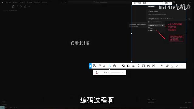
Cursor Tutorial: Building a Python Student Management System from Scratch with AI
Learn Cursor AI editor's Agent, Ask, and Manual modes with a hands-on demo building a Python student management system using Claude, from tech stack selection to deployment.
NotebookLM Usage Limits Are Here: A Complete Guide to Google's Flexible Quota System
Google introduces flexible usage limits for NotebookLM. Learn how the new quota system affects free and paid users, and what it means for the AI industry's shift toward sustainable operations.

AI Agent Performance Optimization in Practice: Three Key Upgrades That Dramatically Improved Output Quality
Deep dive into three key AI Agent upgrades: eliminating silent failures, setting approval gates, and sub-agent parallel processing. Practical tips for building trustworthy automated workflows.