Design Analysis of Tower Crane Spray Dust Suppression Control System Based on Siemens S7-200SMART PLC

Intelligent tower crane spray control system based on S7-200SMART PLC, achieving dual-mode operation and multiple protections.
This article breaks down the design scheme of an intelligent tower crane spray dust suppression control system shared by a Bilibili creator. The system uses the Siemens S7-200SMART PLC as the core, integrating an MCTS water pump speed governor, flow meter, and water pressure gauge to form closed-loop control. Manual mode supports jog debugging and individual actuator control; automatic mode cycles spraying according to preset time periods, run duration, and interval duration, combined with threshold constraints such as upper water flow limit and upper/lower water pressure limits to start and stop, avoiding overpressure or dry running. Multiple alarms including water shortage, high water flow, high/low water pressure, and water pump fault are linked to indicator lights and buzzers; after emergency stop, reset is required to recover. Statistical parameters such as cumulative flow and spray count provide data support for operation and maintenance and water usage accounting. The article also points out that the current scheme is based on a physical model demonstration, and actual deployment needs to consider sensor protection, electromagnetic compatibility, and remote communication expansion.
In construction site dust control scenarios, tower crane spray systems are evolving from manual operation to automation. Bilibili creator "Crazy Electrical Design Drawings" shared a design scheme for an intelligent tower crane spray dust suppression control system based on the Siemens S7-200SMART PLC, combined with an MCTS water pump speed governor, flow meter, and water pressure gauge, achieving manual/automatic dual-mode operation, real-time parameter monitoring, and multiple alarm protections. This article, based on the video content, breaks down the system architecture, control logic, and engineering implementation key points.
System Architecture: PLC as Core, Sensor and Actuator Closed Loop
The scheme uses the Siemens S7-200SMART PLC as the main control unit, integrating the MCTS water pump speed governor, flow meter, and water pressure gauge to form a complete control loop. The PLC is responsible for logic judgment and command issuance, the speed governor drives the water pump, and the flow meter and pressure gauge continuously feed back pipeline network status data, forming a "detect—judge—execute" closed loop.
From an engineering perspective, choosing the S7-200SMART is a pragmatic move: this series has a mature ecosystem in small automation projects, a low programming threshold, and sufficient I/O and communication capabilities to support sensor access and HMI interaction in the spray system. The addition of the MCTS speed governor allows adjustable pump speed, enabling smoother adjustment of spray pressure compared to simple start-stop control, reducing water hammer impact.
S7-200SMART PLC is a compact controller from Siemens for small automation projects, part of the upgraded S7-200 series. It integrates an Ethernet port, RS485 communication port, and multiple digital/analog I/O, supports ladder diagram, statement list, and function block programming, and is widely used in pump stations, HVAC, water treatment, and other scenarios. Its programming software STEP 7-Micro/WIN SMART is available for free, has a low learning curve, and supports communication protocols such as Modbus and PUT/GET, facilitating connection with HMI, inverters, and host computers. For systems like tower crane spray that have few I/O points but require stable operation, this model achieves a good balance between cost and functionality.
MCTS water pump speed governor is a power electronic device used to adjust the speed of water pump motors, typically based on variable frequency or thyristor voltage regulation principles, adjusting pump output by changing the motor input voltage/frequency. Compared to traditional contactor start-stop control, the speed governor enables soft start, stepless speed regulation, and constant pressure water supply, significantly reducing starting current and water hammer effects, while adjusting flow according to actual demand to achieve energy savings. In the spray system, the speed governor receives analog or communication commands from the PLC to dynamically match spray pressure.
Manual Mode: Operation Entry for Debugging and Emergency
After the system is powered on, the HMI provides two operation modes: manual and automatic. Manual mode is for debugging and emergency scenarios, allowing users to perform system start and system stop operations, as well as individually control jog debugging, manual start of spray, and manual stop of each spray actuator.
In manual mode, the HMI simultaneously monitors real-time operating parameters such as water pressure, flow rate, cumulative flow, total spray duration, and total spray count, and feeds back signals including water shortage alarm, high water flow alarm, low water pressure alarm, high water pressure alarm, and water pump fault alarm, while providing system running indication and system stop indication status. The significance of this design is that during debugging, each actuator action can be verified individually, and when a fault occurs, the automatic logic can be bypassed to quickly locate the problem.
Automatic Mode: Dual-Condition Control of Time Window and Threshold
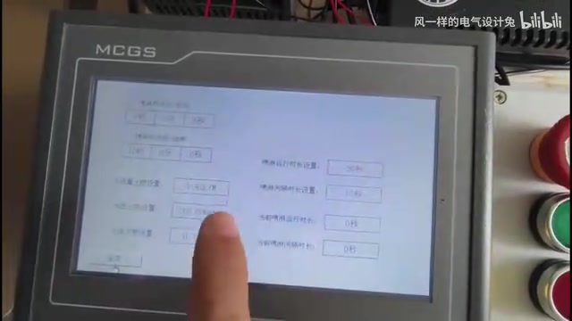
Automatic mode is the core operating logic of the system. Users preset the spray time period, spray run duration, spray interval duration, as well as preset values such as upper water flow limit, upper water pressure limit, and lower water pressure limit. According to the video demonstration, the spray time period can be set with a start of 80, 0 minutes 0 seconds, and an end of real-time 0 minutes 0 seconds; the spray run duration is 30 seconds, and the spray interval duration is 10 seconds.
After real-time detection by the water pressure sensor and flow sensor, the system automatically starts the water pump when the set spray time period is reached; after 30 seconds of spraying, it stops, and after a 10-second interval, it starts again, cycling spraying until the time period ends. This "timing + threshold" dual-condition mechanism ensures periodic coverage of spraying while avoiding abnormal conditions such as overpressure or dry running through constraints on water pressure upper and lower limits and flow upper limit.
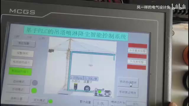
Water pressure gauge and flow meter values, as well as operating parameters such as cumulative flow, total spray duration, and total spray count, are displayed in real time on the HMI, with all operating statuses and alarm signals indicated and protected throughout. This data visualization design allows operators to grasp the working status of the spray system without on-site inspection.
Dry running refers to the water pump continuing to operate when there is no water or insufficient water in the inlet pipe, causing the pump body to lack medium lubrication and cooling, rapidly wearing mechanical seals and impellers, and in severe cases burning out the motor. In spray systems, dry running is usually caused by water source depletion, inlet pipe blockage, or excessive suction lift. This scheme prevents dry running through low water pressure alarm and water shortage alarm linked pump stop: when the water pressure sensor detects pressure below the set lower limit and it persists for a certain time, the PLC determines a water shortage state, stops the pump output and triggers an alarm. After the water source recovers and pressure rises, manual reset is required to restart, avoiding frequent self-starts causing repeated dry running.
Alarms and Protection: Linked Response to Abnormal Conditions
When operating abnormally, the system triggers water shortage alarm, high water flow alarm, low water pressure alarm, high water pressure alarm, or water pump fault alarm; the alarm indicator lights up and the alarm buzzer sounds. Pressing the emergency stop button stops the entire line; after troubleshooting, click the reset button to resume normal operation.
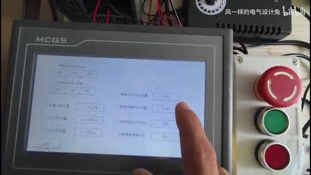
This protection logic covers the most common fault types in spray systems: water shortage corresponds to insufficient water source, low water pressure to pipeline leakage or reduced pump efficiency, high water pressure to pipeline blockage or speed governor failure, and high water flow may indicate sensor abnormality or accidental valve opening. Cross-judgment of multiple signals is more reliable than single-threshold alarms, reducing false alarms and missed alarms.
Water hammer is a phenomenon of severe pressure fluctuations caused by sudden changes in fluid velocity in piping systems. When the water pump stops abruptly or a valve closes quickly, water flow inertia causes high-pressure shock waves in the pipeline, potentially causing pipe fittings to rupture, supports to loosen, or sensors to be damaged. In scenarios with high head and long pipelines such as tower crane spray, the risk of water hammer is particularly prominent. This scheme uses the MCTS speed governor for soft start and soft stop of the water pump, making flow and pressure change gently, weakening water hammer from the source; meanwhile, the high water pressure alarm can promptly cut off the water pump when pressure abnormally surges, forming double protection. In actual engineering, slow-closing check valves or expansion tanks can also be installed to further absorb pressure fluctuations.
Engineering Implementation Insights
Several practices with reference value for similar projects can be extracted from this scheme. First, the clear separation of manual and automatic modes allows debugging and operation to not interfere with each other, reducing on-site debugging risks. Second, parameterizing spray duration and interval enables the system to adapt to different tower crane heights and dust concentration scenarios without modifying the program. Third, the recording of statistical data such as cumulative flow and total spray count provides a basis for subsequent operation and maintenance and water usage accounting.
It should be noted that this scheme is currently demonstrated based on a physical model; actual deployment to construction site environments still requires consideration of sensor protection ratings, electromagnetic compatibility, and remote communication expansion. For developers wishing to reproduce this design, it is recommended to first verify the control logic on a small-scale pipeline, then gradually expand to a real tower crane spray system.
One-line Summary
Intelligent tower crane spray control system based on S7-200SMART PLC, achieving dual-mode operation and multiple protections.
Paragraph Summary
This article breaks down the design scheme of an intelligent tower crane spray dust suppression control system shared by a Bilibili creator. The system uses the Siemens S7-200SMART PLC as the core, integrating an MCTS water pump speed governor, flow meter, and water pressure gauge to form closed-loop control. Manual mode supports jog debugging and individual actuator control; automatic mode cycles spraying according to preset time periods, run duration, and interval duration, combined with threshold constraints such as upper water flow limit and upper/lower water pressure limits to start and stop, avoiding overpressure or dry running. Multiple alarms including water shortage, high water flow, high/low water pressure, and water pump fault are linked to indicator lights and buzzers; after emergency stop, reset is required to recover. Statistical parameters such as cumulative flow and spray count provide data support for operation and maintenance and water usage accounting. The article also points out that the current scheme is based on a physical model demonstration, and actual deployment needs to consider sensor protection, electromagnetic compatibility, and remote communication expansion.
Related articles

FBI and USDA Hit by Cyberattacks: Critical Infrastructure Security Alarms Sound Again
FBI and USDA reportedly hit by cyberattacks; the FBI was breached for the second time in recent months, this time targeting the National Crime Information Center (NCIC). This article analyzes the incident details, NCIC's strategic value, and common security challenges facing government agencies.

How Do UK Grid Battery Storage Systems Make Money?
How UK grid battery storage makes money: stacking frequency response, capacity market, and wholesale arbitrage revenue, plus operational trade-offs and market risks.

Riemann Hypothesis Formally Verified in Lean? Joint Statement Sparks Heated Debate
The Lean community blog published a joint statement on formal verification of the Riemann Hypothesis, sparking heated discussion on Hacker News with 359 points and 263 comments. This article analyzes the background of Lean and mathlib formal verification, polarized community reactions, and why one should not conclude the Riemann Hypothesis has been proven before reading the original text.