Monocular Vision for Box Dimension Measurement: A Practical Guide to Fixing Camera Calibration Reprojection Errors
Practical guide to fixing camera calibration errors in monocular vision-based box dimension measurement.
This article walks through a real-world monocular vision project for measuring box dimensions in logistics, focusing on why camera calibration reprojection errors reach 1.8px and how to reduce them below 0.5px. It covers ChArUco board best practices, sub-pixel refinement, scale ambiguity in monocular systems, and practical tips for marker placement and pose estimation.
Real-World Engineering Scenario: Monocular Vision for Box Dimension Measurement
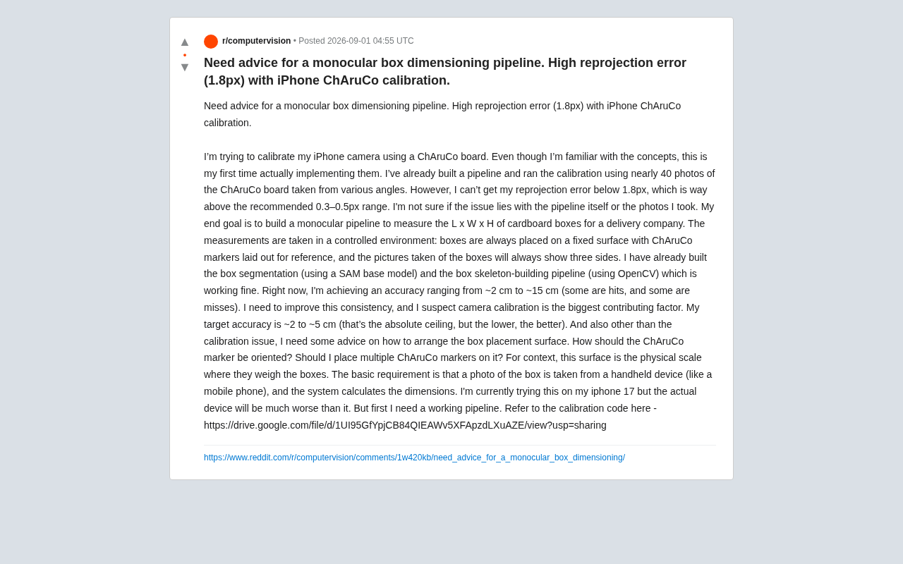
In the logistics and courier industry, automatic measurement of box dimensions (length × width × height) has always been a key factor in improving sorting and billing efficiency. Recently, a developer shared on Reddit their complete experience building a monocular vision box measurement pipeline, along with a problem that plagues many computer vision newcomers: stubbornly high camera calibration reprojection error.
The developer's goal was clear: use a phone to photograph a box placed on a fixed surface, and from a single image showing three visible faces, automatically calculate the box's 3D dimensions. They had already completed box segmentation using SAM (Segment Anything Model) and box skeleton construction using OpenCV — the entire pipeline was basically functional.
SAM is a foundation segmentation model released by Meta AI in 2023, trained on over 1.1 billion masks at massive scale, with zero-shot segmentation capability for arbitrary objects. In this project, SAM is used to precisely segment each visible face of the box from a single photo, providing pixel-level contour information for subsequent skeleton extraction and 3D reconstruction. SAM's advantage is that it doesn't require additional training for the specific category of "boxes" — it only needs a prompt (such as a click or bounding box) to output high-quality segmentation masks. However, SAM only solves the problem of "which pixels belong to the target" and provides no 3D geometric information, so it must work in conjunction with downstream calibration and pose estimation modules.
The problem was accuracy: measurement errors fluctuated between 2cm and 15cm, sometimes accurate, sometimes not. The target accuracy was 2cm to 5cm (lower is better). The developer astutely judged that camera calibration was likely the biggest source of error.
What Does a 1.8px Reprojection Error Actually Mean?
Definition of Reprojection Error
Reprojection error is the core metric for evaluating camera calibration quality. The essence of camera calibration is establishing the mathematical mapping between 3D world coordinates and 2D image pixels. The camera intrinsic matrix contains parameters such as focal length (fx, fy) and principal point coordinates (cx, cy), describing the projection geometry of an ideal pinhole camera. But real lenses also introduce radial and tangential distortion, causing straight lines to bend and deform at image edges. The calibration process captures multiple images of a calibration board with known geometric structure, using algorithms like Zhang's calibration method to simultaneously solve for intrinsics and distortion coefficients.
The calibration process estimates the camera's intrinsic parameters (focal length, principal point, distortion coefficients, etc.), then uses these parameters to reproject known 3D calibration board corner points back onto the image plane. The pixel distance between the projected positions and the actual detected positions is compared, and the average is the reprojection error. Once intrinsics are determined, they remain valid for the same camera as long as the focal length doesn't change — which is exactly why locking your phone's focus is critical: every autofocus adjustment may change the effective focal length, invalidating previous calibration parameters.
The industry consensus is that a good calibration error should be below 0.3–0.5 pixels. Yet this developer, using nearly 40 ChArUco calibration board photos taken from different angles, was stuck at 1.8 pixels — 3 to 5 times higher than the ideal range, enough to amplify into centimeter-level deviations in subsequent 3D measurements.
ChArUco Board Advantages and Common Pitfalls
The ChArUco board is a hybrid of Checkerboard and ArUco calibration patterns, and is currently the mainstream choice for camera calibration. Traditional checkerboard calibration requires all corner points to be detected — if the board is partially occluded or extends beyond the frame, the entire image becomes unusable. ArUco markers are square markers based on binary encoding, where each marker has a unique ID and can be independently recognized. The ChArUco board embeds ArUco markers within the white squares of a checkerboard pattern: the system first identifies ArUco markers to determine global position and ID, then uses the checkerboard corner points between adjacent markers for sub-pixel-level precise localization. This design means that even if the calibration board is partially occluded, the system can still use visible corner points for calibration, while retaining the high precision of checkerboard corner detection (typically achieving sub-pixel accuracy at the 0.05 pixel level).
But even with advanced tools, improper usage can cause errors to skyrocket. Common pitfalls include:
- The calibration board isn't flat enough: Printed on regular paper and placed casually, any warping violates the planarity assumption
- Insufficient angular coverage: 40 photos sounds like a lot, but if the angles are clustered and lack steep tilts and edge coverage, calibration results will still be biased
- Blurry or poorly exposed images: Motion blur from handheld shooting directly damages corner detection accuracy
How to Get Calibration Error Below 0.5px
Improving Data Quality Starting from the Capture Stage
For this type of problem, community experience consistently points to data quality over algorithm tuning. Specific recommendations include:
- Ensure the calibration board is absolutely flat: Mount the ChArUco board on a rigid surface (such as an acrylic sheet or aluminum plate) to eliminate any deformation
- Systematically cover the field of view: When shooting, place the calibration board in all regions of the image — center, corners, edges — and include multiple poses from frontal to steep tilts (approaching 45°). Accurate estimation of distortion coefficients especially depends on data from the edges and corners
- Eliminate motion blur: Use a tripod or increase shutter speed to ensure sharp corner points in every photo
- Lock camera parameters: A phone's autofocus constantly changes the focal length, causing unstable intrinsics. Lock focus and exposure, or maintain the same camera state when shooting both calibration and measurement images
Step-by-Step Review of Calibration Code and Pipeline
The developer mentioned this was their first time implementing a calibration pipeline, so the pipeline itself may also have issues. Worth checking item by item:
- Whether sub-pixel refinement is enabled for corner extraction (
cornerSubPix): OpenCV's cornerSubPix function is a critical step for improving corner detection accuracy. Initial corner detection can only locate positions at integer pixel level, while the sub-pixel refinement algorithm uses the grayscale gradient distribution around corners, iteratively optimizing to refine corner positions to the 0.01 pixel level. The principle is based on an observation: at an ideal corner, the vectors from the corner to neighboring points should be orthogonal to the image gradient at those points. By repeatedly solving the least-squares solution of this orthogonality constraint within a set search window, the algorithm progressively converges on the true corner position. Skipping this step can result in corner localization errors of 0.5–1 pixel, directly causing calibration errors to balloon to several pixels. - Whether the physical dimensions of the calibration board are entered correctly — unit consistency for square edge length and marker edge length
- Whether outlier images have been removed — a few photos with poor detection quality can significantly inflate the average error; these can be filtered by analyzing the individual reprojection error for each image
Inherent Limitations of Monocular Measurement and How to Overcome Them
Scale Ambiguity Is the Fundamental Challenge of Monocular Vision
A critical concept must be highlighted here: monocular vision suffers from scale ambiguity. Scale ambiguity stems from the mathematical nature of perspective projection. When a camera projects a 3D point (X, Y, Z) into a 2D pixel (u, v), the depth information Z is "compressed" away: the points (X, Y, Z) and (kX, kY, kZ) project to exactly the same pixel location for any positive number k. This means that from a single image alone, it's impossible to distinguish between "a box with 0.5m sides at 1 meter away" and "a box with 1m sides at 2 meters away." A single ordinary photo cannot directly recover absolute dimensions — a large box far away and a small box up close may appear the same size in the image.
In stereo vision or structured light systems, the disparity between two viewpoints can recover depth, thereby breaking the scale ambiguity. In a monocular system, external constraints must be introduced. This is precisely the purpose of placing ChArUco markers on the measurement surface in this project: the markers provide a known real-world scale reference. The physical size of the markers is known (e.g., each square has a 30mm edge length), and the system uses the PnP (Perspective-n-Point) algorithm to solve for the camera's pose relative to the marker plane (rotation matrix R and translation vector t). The units of the translation vector are determined by the markers' physical dimensions, thereby converting pixel measurements into real-world millimeter-level measurements, which in turn enables box dimension estimation.
The PnP problem is a classic problem in computer vision: given the world coordinates of n 3D points and their corresponding 2D image projections, solve for the camera's extrinsic parameters. OpenCV provides multiple PnP solvers, including EPnP, P3P, and iterative optimization-based methods. Pose estimation accuracy directly depends on two factors: the accuracy of intrinsic calibration and the precision of corner detection. A 1.8-pixel calibration error means every corner's projected position could be off by nearly 2 pixels. This error gets amplified through the PnP solver into the rotation and translation components of the pose, ultimately manifesting as centimeter-level measurement deviations.
Therefore, calibration errors and pose estimation errors directly and linearly amplify into the final measurement results. This also explains why a 1.8px calibration error can lead to measurement deviations as high as 15cm.
Practical Tips for Marker Plane Layout
In response to the developer's question about "how to arrange ChArUco markers," there are several practical engineering recommendations:
- Use multiple markers or a large-format marker board: A single small marker provides limited pose constraints. Laying out a marker grid covering the entire weighing surface can significantly improve the stability of plane pose estimation, especially when the box occludes some markers and redundancy is needed
- Markers must be coplanar with the box's bottom face: The box sits on the marker plane, and the system can leverage the strong constraint that "the box bottom is coplanar with the marker plane" to anchor the scale. Ensure markers are flat and flush with the surface
- Align the marker coordinate system with the measurement coordinate system: Making the marker coordinate system direction consistent with the desired measurement coordinate system simplifies subsequent geometric calculations and reduces errors introduced by coordinate transformations
Overall Recommendations for Similar Vision Measurement Projects
Looking at the big picture, this project's technical approach is sound: SAM for segmentation, OpenCV for skeleton construction, and ChArUco for scale reference — a clean architecture. To achieve the 2–5cm target accuracy, focus should be placed on the following areas:
- Prioritize calibration quality — get the reprojection error below 0.5px, as this is the foundation of accuracy
- Strengthen the marker plane pose constraints — use multi-marker grids to improve stability
- Plan for equipment degradation — production environment cameras are often lower quality, so both calibration and algorithms need robustness margins built in
- Build a quantitative evaluation dataset — continuously verify error distribution using boxes with known real dimensions, rather than relying on anecdotal observations
Monocular dimension measurement may seem simple, but it's actually a systems engineering challenge that is extremely sensitive to calibration accuracy, geometric constraints, and engineering details. This developer's experience reinforces a golden rule in computer vision: Before agonizing over algorithms, make sure your calibration and data are clean.
Related articles

Chain of Thought Isn't Just for AI: How Humans Can Use CoT to Improve Thinking Quality
Chain of Thought isn't just a prompt trick for large models. Starting from a Hacker News discussion, this article analyzes why CoT works for human thinking too, breaks down actionable ways to transfer it, and highlights the key differences between human CoT and machine CoT.
Cloudflare Teams Up with OpenAI: Closi…
Cloudflare Teams Up with OpenAI: Closing the Loop from Vulnerability Discovery to Defense with AI
Cloudflare uses OpenAI Daybreak to investigate security vulnerabilities and generate reviewable remediation plans, while developers use Codex to boost coding efficiency and quality.

Orca Multi-Agent Orchestration in Practice: A Guide to Parallel Collaboration with Claude and Codex
Orca is Stable AI's free open-source agent workbench supporting 34 agents like Claude Code and Codex in parallel. Learn its Git worktree isolation, multi-model orchestration, and mobile management.