DIY Four-Wheel Skid-Steer Off-Road Robot: A Full Hands-On Log of a Hoverboard Motor Build

A DIY four-wheel skid-steer off-road robot built from hoverboard motors, ODrive, and Raspberry Pi 5.
A Reddit hobbyist shares the first outdoor test of a homemade four-wheel skid-steer robot built from hoverboard hub motors, ODrive boards, and a Raspberry Pi 5. The article details the hardware, 4G teleoperation, the friction-dependent nature of skid steering, and a full roadmap toward ROS2/Nav2 autonomous navigation.
From Workbench to the Outdoors: A Real-World Off-Road Test
A hobbyist from the Reddit r/robotics community (user /u/NiamorroMilky) recently shared the results of the first outdoor test of his homemade four-wheel skid-steer off-road robot. Before this, the machine had only been debugged on the workbench—this was the first time it truly rolled out of the indoors and ran on real terrain.
For robotics DIY enthusiasts, this is a fairly representative project: no expensive commercial chassis, just a pile of consumer-grade components assembled into a genuinely functional mobile platform.
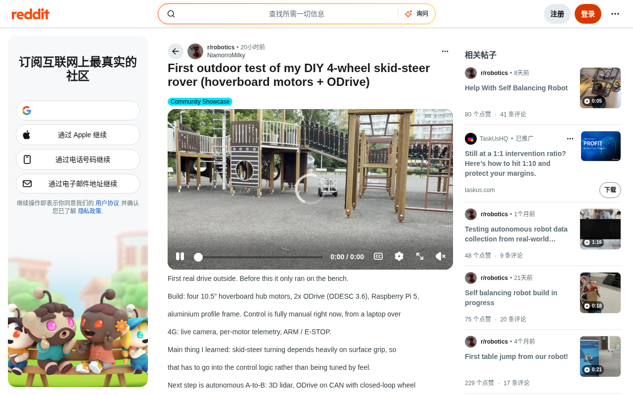
Hardware Configuration: A Clever Combination of Low-Cost Components
The core makeup of this skid-steer robot fully embodies the Maker spirit of "open-source hardware + repurposing waste."
Powertrain
-
Four 10.5-inch hoverboard hub motors: There's a deep economic and technical logic behind why hoverboard hub motors have become the "star part" of the robotics DIY community. The 2015-2016 hoverboard craze spawned large-scale production worldwide, and Chinese manufacturers optimized highly integrated, extremely low-cost brushless DC hub motor solutions for this consumer market. A typical hoverboard hub motor has a rated power of 250-350W, with built-in Hall sensors providing rotor position feedback, and a peak torque of up to 15-20 N·m—while the market price of a single motor often stays below $30-50. By comparison, an industrial servo motor with equivalent torque output might cost hundreds or even thousands of dollars. Hub motors integrate the motor, reduction mechanism (in some models), and tire into one unit, eliminating transmission components like chains, belts, or couplings, and greatly reducing mechanical design complexity. It is precisely this "cheap but good enough" characteristic that has made them widely popular in the open-source robotics community, spawning a large number of mobile platform projects based on hoverboard parts. The four-motor, four-wheel-drive configuration provides solid off-road capability.
-
2 ODrive (ODESC 3.6) driver boards: ODrive was launched by Oskar Stenmark in 2016, aiming to provide a high-performance brushless motor FOC (Field-Oriented Control) drive solution for hobbyist and semi-professional applications. The FOC algorithm decomposes three-phase currents into torque and flux components and controls them separately, achieving far smoother torque and greater efficiency than traditional PWM square-wave drives, and it supports encoder closed-loop position, velocity, and current control modes. The ODESC 3.6 is a compatible derivative developed by the Chinese community; it maintains software compatibility while optimizing PCB layout and thermal design at a more competitive price. Each board drives two motors, achieving precise closed-loop current and speed control.
Computing and Structure
-
Raspberry Pi 5: Serving as the main control brain, it handles communication, remote control command processing, and telemetry data transmission. The biggest improvement of the Raspberry Pi 5 over its predecessor is its Broadcom BCM2712 quad-core Cortex-A76 processor, with a clock speed of up to 2.4 GHz and greatly improved floating-point performance—which is especially critical for robotics applications that need to run ROS2 nodes in real time, process sensor data streams, and perform Kalman filtering. Its PCIe 2.0 interface also leaves room for future expansion of high-speed peripherals (such as an NVMe SSD for storing LiDAR point cloud data).
-
Aluminum extrusion frame: The chassis is built from industrial aluminum extrusions commonly used in industry, balancing strength, expandability, and ease of assembly. Industrial aluminum extrusions (such as the European standard 2020, 3030 series) allow nuts and brackets to be mounted at any position thanks to their standardized T-slot design, enabling structural adjustments without drilling or welding. This characteristic is extremely practical for DIY projects that require frequent iteration of the mechanical layout.
The biggest highlight of this combination is "doing big things with little money"—bypassing expensive industrial servo systems and using mature solutions from the open-source ecosystem to build a fully functional mobile robot platform.
Current Control Method: 4G Remote Manual Teleoperation
Currently, this robot is in a fully manual control stage, with the author operating it remotely from a laptop over a 4G network. Choosing a 4G cellular network over local Wi-Fi for robot teleoperation requires a trade-off between bandwidth, latency, and coverage. A 4G LTE network's theoretical peak downlink can reach 150 Mbps, sufficient to support HD video streaming, but its actual end-to-end latency is typically between 50-150 milliseconds—an order of magnitude worse than local Wi-Fi's 1-5 milliseconds. For manual teleoperation scenarios, 150ms of latency is on the borderline of what humans can tolerate; it is barely usable in open, low-speed off-road environments, but it significantly increases the difficulty of control in high-speed or obstacle-dense scenarios.
From a protocol perspective, common solutions for remote robot control include low-latency video + data channel schemes based on WebRTC, and schemes that virtually extend the robot's LAN to a remote end via a VPN tunnel (such as ZeroTier, WireGuard). The advantage of the latter is that ROS2's DDS communication can run transparently across the network, allowing the RViz visualization tool in the local development environment to directly subscribe to topics published by the remote robot, greatly reducing debugging complexity.
This teleoperation system already has quite practical features:
- Real-time camera feed: Lets the operator remotely "see" the environment the robot is in.
- Independent telemetry data for all four motors: Real-time monitoring of each motor's operating status, making debugging and troubleshooting convenient.
- ARM / E-STOP mechanism: The arming and emergency stop functions are a key part of safety design. More critically, cellular networks carry a risk of brief disconnection during cell tower handovers, which is exactly why the E-STOP safety mechanism is indispensable—when the control link is interrupted, the robot must be able to safely stop in the absence of commands, rather than continuing to execute the last velocity command. In engineering terms, this is usually implemented through a "heartbeat" mechanism: the control end continuously sends a keep-alive signal to the robot at a fixed frequency (such as 10Hz), and the robot side sets a timeout threshold (such as 300ms). Once the timeout is exceeded without receiving a heartbeat, the E-STOP is triggered automatically. This mechanism runs independently of the main control logic and has the highest priority.
Choosing 4G over local Wi-Fi means this open-source robot can theoretically operate at ranges far beyond line of sight, leaving ample room for imagination for future outdoor autonomous navigation. After ROS2 autonomous navigation is introduced in the future, 4G's role will be downgraded from a real-time control channel to a monitoring and intervention channel, and latency sensitivity will drop significantly.
Key Takeaway: Skid-Steer Steering Depends Heavily on Ground Friction
The most important technical insight from this outdoor test is: the turning behavior of skid-steer is heavily dependent on ground traction.
The Historical Origins and Kinematic Essence of Skid-Steer
Skid-steer is a steering mechanism derived from military tracked vehicles, with a history that traces back to WWI-era tank designs—the Mark I tank achieved steering through the primitive differential principle of braking one side of its tracks. The kinematic model of modern skid-steer is built on the concept of the "Instantaneous Center of Rotation (ICR)": by controlling the left-to-right wheel speed ratio, the ICR can theoretically be moved continuously from infinity (straight travel) to the center of the vehicle body (turning in place), giving skid-steer platforms extremely high maneuverability that Ackermann-steered vehicles cannot structurally achieve.
By contrast, Ackermann steering (the front-wheel steering method of ordinary cars) uses geometric constraints to ensure that all wheels roll purely around the same instantaneous center of rotation, producing almost no lateral sliding; skid-steer, on the other hand, relies on actively creating a speed difference between the left and right wheels, forcing the outer wheels to "drag" the inner wheels and forcibly change heading, and there must be lateral friction doing work between the tires and the ground. This fundamental difference puts skid-steer at a disadvantage across three dimensions—energy efficiency, tire wear, and position estimation accuracy—but in return provides zero-turning-radius (turn-in-place) capability and an extremely simple mechanical structure. There's no need for steering tie rods, steering knuckles, or servo steering, greatly reducing the number of moving parts and actually benefiting reliability in outdoor off-road scenarios.
It's worth mentioning that on extremely soft ground (such as deep sand or mud), the "plowing" phenomenon of tires during a turn causes ground deformation, which in turn changes the friction coefficient for the next step, forming a positive feedback loop of control disturbance—this is one of the main challenges for skid-steer platforms in extreme off-road scenarios. However, the core cost is that tires must slide laterally on the ground when turning; this "slipping" consumes energy and also makes the turning radius and angular velocity highly dependent on the ground friction coefficient.
Odometry Inaccuracy and the Necessity of Sensor Fusion
In the field of robot control, the lateral sliding characteristic of skid-steer also leads to a severe drop in odometry accuracy. Traditional wheel odometry accumulates wheel rotation counts via encoders and, combined with the known wheel radius and wheelbase, uses a kinematic model to estimate changes in the robot's position and orientation. This method has acceptable accuracy under ideal conditions, but for a skid-steer robot, the lateral sliding of the tires during a turn cannot be perceived by the encoders—encoders can only sense the amount of shaft rotation, not the actual direction of tire displacement on the ground. This means each turn injects unquantifiable error into the pose estimate, and this error continually accumulates with distance traveled, forming the classic "drift" phenomenon.
In practice, this problem is usually mitigated through multi-sensor fusion and Kalman filtering. The Kalman Filter was proposed by Hungarian-born engineer Rudolf Kálmán in 1960 at NASA's Ames Research Center, originally used for orbit estimation in the Apollo program, and is a classic mathematical framework for solving the fusion of noisy sensor data. Its core idea is: establish a kinematic model of the system for state prediction (the prediction step), then use actual sensor observations to weightedly correct the prediction (the update step), with the weights determined by the noise covariance matrix of each sensor—the lower a sensor's noise, the higher its confidence weight in the fusion. This alternating iterative "predict-update" process makes the fused state estimate theoretically more accurate than any single sensor.
The IMU (Inertial Measurement Unit) typically consists of a three-axis MEMS accelerometer and a three-axis MEMS gyroscope, outputting data at frequencies from hundreds to thousands of hertz. The gyroscope measures angular velocity, and integrating it can theoretically recover the rotation angle, but because MEMS gyroscopes have inherent random walk error, long-term integration causes the angle estimate to drift continuously—this is precisely why an IMU cannot serve as a standalone long-term positioning sensor, and is the technical prerequisite for why it must be fused with other sensors.
For skid-steer robots, the complementarity of the IMU and wheel odometry is extremely ideal: wheel odometry drifts very little during straight travel but becomes inaccurate during turns due to lateral sliding; the IMU accurately senses rotation over short periods but has long-term drift. Their error characteristics happen to form a mutually complementary advantage. Specifically, the IMU can accurately sense the rotation rate during a turn, compensating for the blind spot of encoder odometry during skid steering; wheel odometry provides reliable displacement integration during straight travel, suppressing the IMU's cumulative drift.
The Extended Kalman Filter (EKF) extends the standard Kalman filter to nonlinear systems like robots by linearizing the nonlinear motion model through a first-order Taylor expansion, becoming the engineering standard choice for robot pose state estimation. ROS2's robot_localization package implements multi-sensor EKF/UKF fusion; developers only need to declare each sensor's input topic and corresponding state variables via a YAML configuration file to build a complete fusion pipeline, making it an important foundational component for this project's future navigation upgrade. This is also precisely why the project lists 3D LiDAR as a necessary upgrade in the next phase—odometry based on encoders alone simply cannot support reliable autonomous navigation, and external absolute observations must be introduced to constrain pose drift.
Therefore, on different surfaces such as concrete, grass, dirt, and gravel, the same motor commands produce entirely different turning effects. From this, the author draws an important conclusion:
"The ground traction factor must be incorporated into the control logic, and cannot be tuned by the operator's feel and experience."
This is precisely the key step from "toy-grade" to "engineering-grade." A truly reliable mobile robot needs to model and compensate for different ground conditions at the control algorithm level, rather than relying on the operator's on-the-spot judgment.
Next Steps: Toward ROS2 Autonomous Navigation
The author has planned a clear advanced roadmap, with the goal of achieving fully autonomous navigation from point A to point B. The tech stack covers three layers: perception, control, and planning.
Perception Layer
- 3D LiDAR: Builds a 3D point cloud map of the surrounding environment, achieving obstacle detection and autonomous localization—the perceptual foundation of autonomous movement.
The sharp drop in 3D LiDAR prices is one of the most disruptive hardware trends in the robotics field in recent years. In the early 2010s, the Velodyne HDL-64E was the industry benchmark, priced at up to $75,000—affordable only to top research institutions and automakers. This landscape was completely broken by several forces: the maturity of solid-state LiDAR and MEMS scanning technology eliminated mechanical rotating parts, greatly reducing manufacturing costs and reliability risks; the large-scale entry of Chinese manufacturers (such as RoboSense, Hesai, and Livox) brought highly competitive pricing; and the autonomous driving investment boom forced the entire supply chain to reduce costs and improve efficiency across the board. By 2023-2024, consumer-grade 3D LiDAR (such as the Livox Mid-360 and RoboSense RS-LiDAR-16) had dropped to the $500-1000 range, with some entry-level models even below $200. Notably, the non-repetitive scanning pattern used by Livox differs from the uniform rosette scanning of traditional mechanical rotating LiDAR; its point cloud density on stationary targets increases with integration time, a characteristic especially beneficial for fine mapping in low-speed or hovering states.
This means that SLAM (Simultaneous Localization and Mapping) technology, which previously existed only in papers and corporate labs, can now be truly implemented in personal garage projects. SLAM technology processes LiDAR point clouds in real time, incrementally building a map of the environment while the robot moves and estimating its own pose within the map—two processes that are interdependent and solved collaboratively, forming a chicken-and-egg problem of "you need a map to localize, and you need to localize to map." Modern LiDAR SLAM systems (such as LOAM, LIO-SAM, Fast-LIO2) extract edge and planar features from point clouds, use inter-frame feature matching to compute pose changes, and then use back-end graph optimization to eliminate cumulative errors, achieving centimeter-level real-time mapping and localization—the perceptual core of autonomous navigation.
Control Layer
-
Switching ODrive to CAN bus communication: The CAN (Controller Area Network) bus was developed by Bosch in 1983, originally for communication between ECUs (Electronic Control Units) in automotive electronic systems, with a core design philosophy of "high reliability, low wiring complexity, deterministic real-time transmission." For multi-motor robot systems, the advantages the CAN bus brings are systemic: all nodes share two differential signal lines (CANH/CANL), and whether connecting 2 or 10 motor controllers, the trunk line complexity stays the same; the priority-based multi-master arbitration mechanism (CSMA/CA) allows any node to initiate communication with no single-point bottleneck; and the differential signal has natural resistance to electromagnetic interference, which is especially important in robot environments where motor drivers generate strong electromagnetic noise. CAN FD (Flexible Data-rate) is an upgraded version of CAN that, while maintaining backward compatibility, extends the maximum data frame length from 8 bytes to 64 bytes, boosting payload bandwidth to 8 times the original—enough to transmit a complete motor state data packet in a single frame.
Most critically, the CAN bus supports broadcast-style synchronized commands—a single velocity command frame sent by the main controller can be received and executed by all motor controllers at the same instant, with time synchronization accuracy at the microsecond level. By comparison, in schemes using multiple UART or USB serial channels, there is a timing difference in command transmission for each motor controller, which causes noticeable left-right wheel coordination errors during high-speed motion, affecting steering accuracy and vehicle stability. ODrive has had a built-in CAN interface since v3.6; combined with ROS2's
can_bridgenode, this enables an extremely concise and efficient multi-motor control architecture. -
Closed-loop wheel control: Applying precise closed-loop feedback to the rotation speed of each wheel also happens to align perfectly with the idea of "incorporating ground friction into the control logic." Closed-loop speed control uses a PID controller to continuously compare the target speed with the actual speed fed back by the encoder, automatically adjusting the motor drive current to eliminate the error. This means when one side's wheels get stuck on a low-friction surface (such as wet grass), the controller automatically increases that wheel's drive current to maintain the target speed, partially compensating for heading deviations caused by uneven ground friction. On this basis, more advanced adaptive control schemes can estimate the ground friction coefficient of each wheel in real time (using online identification based on the relationship between drive current and actual speed) and dynamically adjust the velocity command distribution of skid steering, further improving steering accuracy on complex terrain.
Planning Layer
-
ROS2 / Nav2 navigation framework: ROS2 is a complete rebuild of ROS1, with the core improvement being the introduction of DDS (Data Distribution Service) as the communication middleware, providing real-time guarantees, a decentralized architecture, and a more robust security mechanism. Unlike ROS1, which relies on a centralized
rosmasternode, ROS2's DDS discovery mechanism allows nodes to discover each other autonomously without a central coordinator, so single-point failures no longer paralyze the entire system—which is especially important for safety-critical outdoor robotics applications.Nav2 is the officially supported navigation framework for ROS2. Unlike
move_basein the ROS1 era, which used a single-threaded state machine architecture, Nav2 introduces the Behavior Tree (BT) as the core paradigm for task scheduling.Behavior trees originated in electronic game AI development in the 2000s, first proposed by engineers at Crystal Dynamics for designing NPC behavior in the Tomb Raider series, and later systematically studied in academia and the robotics field. The essential difference from state machines is: in a state machine, the state transition logic is scattered across the state nodes and becomes exponentially more complex as the number of states grows (the so-called "state explosion" problem—a state machine with n states needs to manage up to n² transition edges); a behavior tree, on the other hand, uses just a few types of composite nodes—Sequence, Fallback, Parallel, and Decorator—to uniformly manage all logic flow in a tree-shaped hierarchical structure, so adding a new behavior only requires attaching a new leaf node without modifying existing logic, achieving "plug-and-play" reuse of behaviors.
More importantly, behavior trees adopt a "reactive" execution model: tree execution starts from the root node, and each control cycle re-"ticks" (triggers evaluation) downward from the root. Any high-priority Fallback node can immediately preempt a lower-priority task in the current cycle—while the robot is executing a navigation task, a safety monitoring subtree (such as collision detection or battery alarm) can immediately trigger emergency braking within the same control cycle in which a threat is detected, without waiting for the navigation state machine to complete the execution of its current state. This preemptive capability gives behavior trees a clear advantage over traditional state machines in safety-critical systems.
In Nav2, a typical navigation behavior tree might include: first attempting to compute a global path; if the path is blocked by obstacles, triggering wait-for-clearance or detour recovery behaviors, while executing battery monitoring and safety fence check subtrees in parallel. Nav2's complete tech stack covers:
- slam_toolbox: Graph-optimization-based 2D/3D real-time SLAM mapping
- AMCL (Adaptive Monte Carlo Localization): Particle-filter-based localization on a known map
- NavFn / Smac Planner: Global path planning (Dijkstra/A* algorithms)
- DWB / MPPI local controllers: Real-time dynamic window or model predictive path integral obstacle avoidance
- Costmap2D: Sensor-data-based obstacle cost map management
Nav2 officially also provides several predefined behavior tree XML templates, allowing developers to customize the robot's high-level behavior logic simply by editing XML files without modifying any C++ code, greatly lowering the development barrier for autonomous navigation systems.
From "manual teleoperation" to "perception + planning + closed-loop control," this roadmap comprehensively covers all the core modules required for an autonomous mobile robot.
Why This Project Is Worth Watching
Although the author modestly says this DIY off-road robot is "still in its early stages," it precisely demonstrates the tremendous vitality of today's open-source robotics ecosystem:
- Greatly lowered hardware barriers: Hoverboard motors, ODrive driver boards, Raspberry Pi, aluminum extrusions—all core components can be purchased at relatively low prices.
- An increasingly mature software ecosystem: Open-source projects like ODrive and ROS2/Nav2 allow individual developers to stand on the shoulders of industrial-grade software frameworks.
- The growth of engineering thinking: The author distilled the conclusion that "ground friction must enter the control logic" from real-world testing, embodying the evolution from experience-driven to model-driven approaches.
For enthusiasts looking to get started in mobile robot development, this project provides an extremely valuable roadmap: first build a functional platform with low-cost hardware, start with manual teleoperation to validate the mechanical and power systems, then gradually add perceptual capabilities, upgrade the communication protocol, and introduce an autonomous navigation framework.
As 3D LiDAR prices continue to fall and the ROS2 ecosystem grows increasingly complete, "garage-grade" autonomous robot projects will only become more numerous—and increasingly close to professional standards.
Key Points
- Skid-steer platforms trade mechanical simplicity for a high dependence on ground friction, a characteristic that must be explicitly modeled and handled at the control algorithm level rather than compensated for by operator experience.
- The reuse of "surplus" consumer electronics parts, such as hoverboard motors and ODrive driver boards, forms the core logic of modern DIY robotics economics.
- The upgrade path from manual teleoperation to autonomous navigation is clear: CAN bus synchronized communication → IMU + odometry EKF fusion → LiDAR SLAM mapping and localization → Nav2 behavior tree planning, with each step supported by a mature open-source toolchain.
- The order-of-magnitude drop in 3D LiDAR prices is a key driver making "garage-grade" autonomous navigation projects a reality, and this trend continues.
Related articles

Meta vs. Publishers: The AI Data Battle Over Terms of Service Changes and the Future of the Internet
Meta changed its business account terms to allow AI training on linked website data, sparking backlash from publishers and creators. Industry groups demanded negotiations, forcing Meta to remove 'training' wording and delay the effective date. The dispute reveals the deeper battle over data authorization and the future of the internet in the AI era.

When Outside Xbox Meets Blood on the Clocktower: A Legion Match in Minecraft
Outside Xbox guests Ellen and Mike play Minecraft Blood on the Clocktower in a Legion game. How can three good players fight an evil majority amid information noise? This article breaks down Legion mechanics, information-role mind games, and the endgame reversal.

Kimi K3.1 Hands-On Test: Open-Source Model Nears Opus, Video Generation Steals the Show
Kimi K3.1 completed motion graphics, 3D rendering, mini-games, and video generation in a live test. Analysis of its 2.8T MoE architecture, gap vs Opus/GPT, and hidden video generation.