GPT-6 Astra Autonomously Designs a 6-Layer F405 FPV Flight Controller PCB: A Full Walkthrough
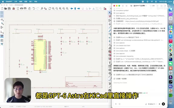
GPT-6 Astra autonomously designed a 6-layer F405 FPV flight controller PCB, but real-world validation is still pending.
A Bilibili creator connected GPT-6 Astra to an EDA tool and had it independently complete a full FPV drone flight controller PCB design — covering schematics, 6-layer layout, routing, and self-directed ERC/DRC checks with iterative fixes. The model exported a complete production file set including Gerber, drill, BOM, pick-and-place, and STEP files, theoretically ready for fabrication. The process took 3 hours 14 minutes and consumed ~52 million tokens at high reasoning intensity. However, the design remains unvalidated; real engineering challenges like signal integrity, power ripple, and EMI can only be confirmed through physical testing.
Pushing AI to Its Limits in Hardware Design
After large language models proved capable of writing code, generating images, and producing videos, hardware design became the next frontier to conquer. A Bilibili content creator recently connected GPT-6 Astra directly to an EDA tool (referred to in the video as Gitkad) and had it independently design an FPV drone flight controller PCB from scratch — with zero human intervention throughout.
This wasn't a simple schematic generation exercise. It covered the full workflow: circuit schematics, PCB layout, routing, and component placement. More importantly, the model had to run its own rule checks, identify problems, and fix them — this closed-loop capability is where the real difficulty of hardware design lies.
A Complete Pipeline from Schematic to 6-Layer Board
The entire workflow can be broken into several stages: first, drawing the circuit schematic and defining the connections between the F405 MCU and its peripheral components; then moving into the PCB phase, which includes layout planning, component placement, and routing. All of these steps were performed directly by GPT-6 Astra within the EDA tool.
The most impressive demonstration of truly autonomous design came after the initial layout was complete: the model ran both ERC (Electrical Rules Check) and DRC (Design Rules Check) on its own. These two checks are the core mechanisms hardware engineers use to catch wiring errors, spacing violations, and footprint conflicts. The model then used the results to revise the schematic and layout, creating a self-iterating "design → check → fix" loop rather than simply outputting a one-shot result.
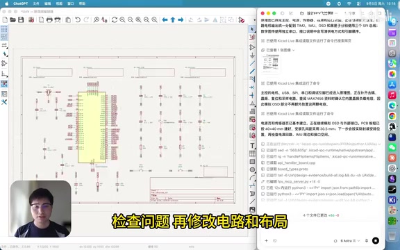
The final output is a 6-layer F405 flight controller board. A 6-layer stackup implies more complex layer arrangement and higher routing density. For a flight controller — a board with dense signal traces and strict power integrity requirements — autonomous handling of a 6-layer design exceeds what most people would expect from current AI hardware capabilities.
ERC and DRC explained: ERC (Electrical Rules Check) and DRC (Design Rules Check) are two independent automated verification stages in EDA tools. ERC checks schematic-level logic errors — unconnected pins, signal shorts, power network conflicts, and so on. DRC validates physical constraints at the PCB level: whether trace clearances meet manufacturing specs, whether via annular rings are compliant, whether copper pours overlap illegally. In professional engineering workflows, both checks typically require engineers to manually review reports and locate issues one by one. The ability for an AI to parse error reports and trace them back to specific corrections in the schematic or layout is the highest-value technical demonstration in this entire exercise — it requires the model to simultaneously understand circuit logic, spatial constraints, and manufacturing rules, then map abstract error descriptions back to concrete design actions.
6-layer stackup basics: Compared to a standard 2-layer board, a 6-layer board typically interleaves signal layers with dedicated power and ground planes. These planes dramatically reduce power impedance and improve signal return paths, suppressing interference on high-speed signals. A flight controller integrates IMUs, MCUs, and wireless modules — all sensitive to signal integrity — making a 6-layer structure the standard choice for balancing compact dimensions with electrical performance.
Complete Deliverables: Ready to Send to Fabrication
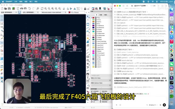
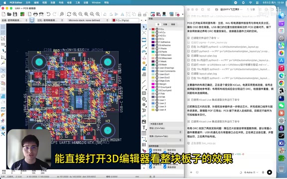
Once the design was complete, GPT-6 Astra exported a full production file package: Gerber files, drill files, BOM (Bill of Materials), pick-and-place coordinates, and a STEP 3D model file. This set covers essentially everything needed to go from factory prototype to SMT production.
The STEP file can be opened directly in a 3D editor to inspect the board's physical appearance and verify component footprints and spatial layout. In terms of deliverable completeness, this board is theoretically ready to be sent directly to a fab house.
What these files are: Gerber files are the universal standard format for PCB manufacturing, established by Gerber Scientific in the 1960s–70s and still the primary format accepted by factories today. Each Gerber file corresponds to one physical layer of the PCB (top copper, solder mask, silkscreen, etc.), which the factory uses to control photoplotters or etching equipment. Drill files (typically in Excellon format) separately describe the positions and diameters of all through-holes and vias. The BOM (Bill of Materials) lists the part number, footprint, and quantity for every component reference designator — the basis for procurement and kitting. The pick-and-place file records the center coordinates and rotation angle of each SMD component for the SMT machine to automatically pick and accurately place parts. Having this complete file set means the factory can go straight to production without needing to request additional information from the designer.
Time and Compute Cost: 3 Hours, ~52 Million Tokens
The resource consumption figures are worth noting. According to the creator's record, the entire design process took 3 hours and 14 minutes, with the model's reasoning intensity set to "high," consuming approximately 52 million tokens in total.
This figure vividly reflects the complexity of a hardware design task. Unlike writing a snippet of code or generating an article, PCB design requires the model to continuously maintain a large amount of context: net connections, component positions, routing paths, design constraints, and more. Any error in one step will surface during subsequent checks. The 52 million token count indicates that enormous compute was spent on repeated reasoning, checking, and correction — which also explains why the process took over three hours.
The Critical Unknown: Will It Actually Work When Powered On?
It's important to stay clear-eyed: this demonstration currently remains at the "design stage." The creator explicitly noted that the board has not yet been prototyped, and whether it will operate reliably can only be confirmed through real-world testing.
This is the biggest open question in the entire case. Passing ERC/DRC checks means the design has no obvious rule violations — but it does not guarantee correct circuit logic or adequate performance. A flight controller involves gyroscope signal integrity, power supply ripple, EMI interference, and a host of other real-world engineering challenges that typically only surface during physical testing. In other words, the AI has handed in an answer sheet that looks professional, but the real exam doesn't begin until the board is soldered up and powered on.
Even so, the significance of this case lies in demonstrating that a large model can autonomously operate within professional engineering tools and maintain a genuine self-verification capability. If follow-up physical testing confirms the board is functional, the potential for AI-assisted hardware design will expand dramatically. Until then, the rational stance is to treat this as an exciting exploration of capability boundaries — not a production-ready solution.
Real engineering challenges beyond rule checks: The practical hurdles for a flight controller go far beyond passing DRC. Take the IMU (gyroscope) as an example: its output signals are high-frequency and low-amplitude, making them extremely sensitive to PCB trace impedance continuity and the placement of nearby decoupling capacitors — a suboptimal layout can cause attitude data to drift. On the power side, flight controllers typically need to supply multiple clean, low-ripple rails to the MCU, sensors, and wireless modules; how power planes are split and how filter components are selected and placed directly affects system stability. EMI is even harder to fully predict at the simulation stage — radiation from high-frequency switching power supplies and harmonics from motor drive signals can couple into sensor circuits, requiring a combination of shielding, ground plane copper pours, and ferrite bead filtering to suppress. None of these issues leave any trace in an ERC/DRC report; they only reveal themselves after soldering, powering up, and connecting real flight control software — which is precisely why the industry remains cautious about whether an "AI-designed board" can succeed on the first spin.
Related articles
Can KoboldCpp Replace Ollama? A Deep Dive into Local AI Tool Control
KoboldCpp and Ollama both run on llama.cpp. This deep dive compares control granularity, default settings, context shifting, and exclusive features to help you decide which local AI tool to use.

Running Local LLMs on a Regular Home PC: Which Models Are Actually Worth Keeping?
A Bilibili creator tested local LLMs on a Geekom mini PC with 24GB VRAM. MoE models like Gemma 26B hit 31 tok/s; Qwen3 27B runs at 14 tok/s — no workstation needed.

Structural Infertility: Why This Generation Finds Having Children Nearly Impossible
Vox podcast interview with journalist Anna-Louise Sussman unpacks "structural infertility": how housing costs, childcare, the anxious class, climate anxiety, and financialized fertility tech make family formation feel impossible.